Marx Generator
(including measurement of the output)
|
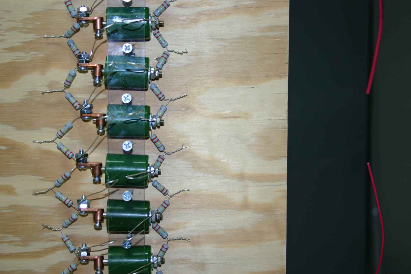
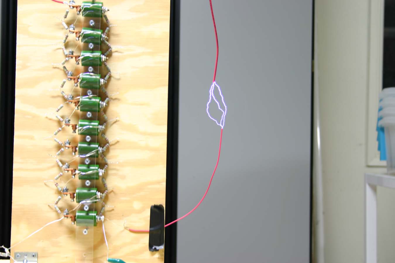
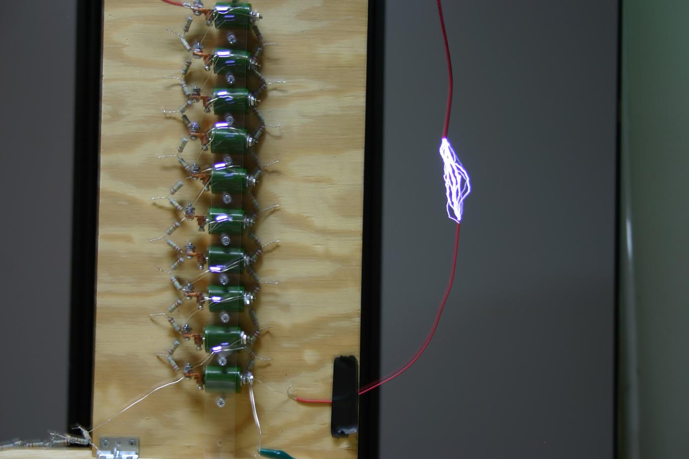
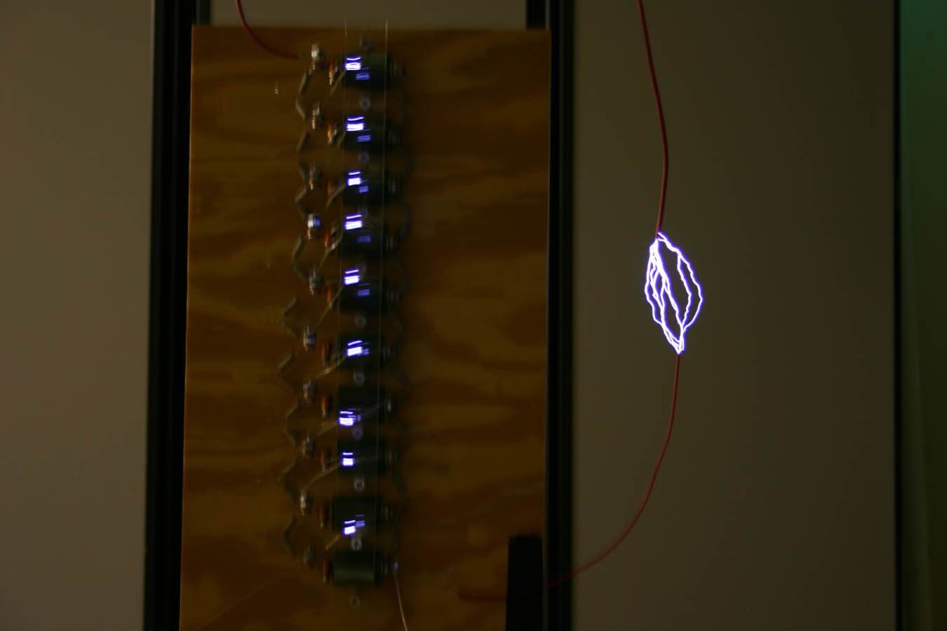
I decided to construct a 10 stage Marx Generator. Each capacitor is 470pf at 30kV. The resistance between each stage was 2 Mega Ohms. The charging supply was a NST halfwave rectified. During the first several tests, I was only able to achieve about 2 inches. However, after adjusting the spark gaps I was finally able to achieve a 5 inch spark, which amounts to around 125kV on the output. There were many sharp points in the setup, so this was probably limiting the output somewhat.
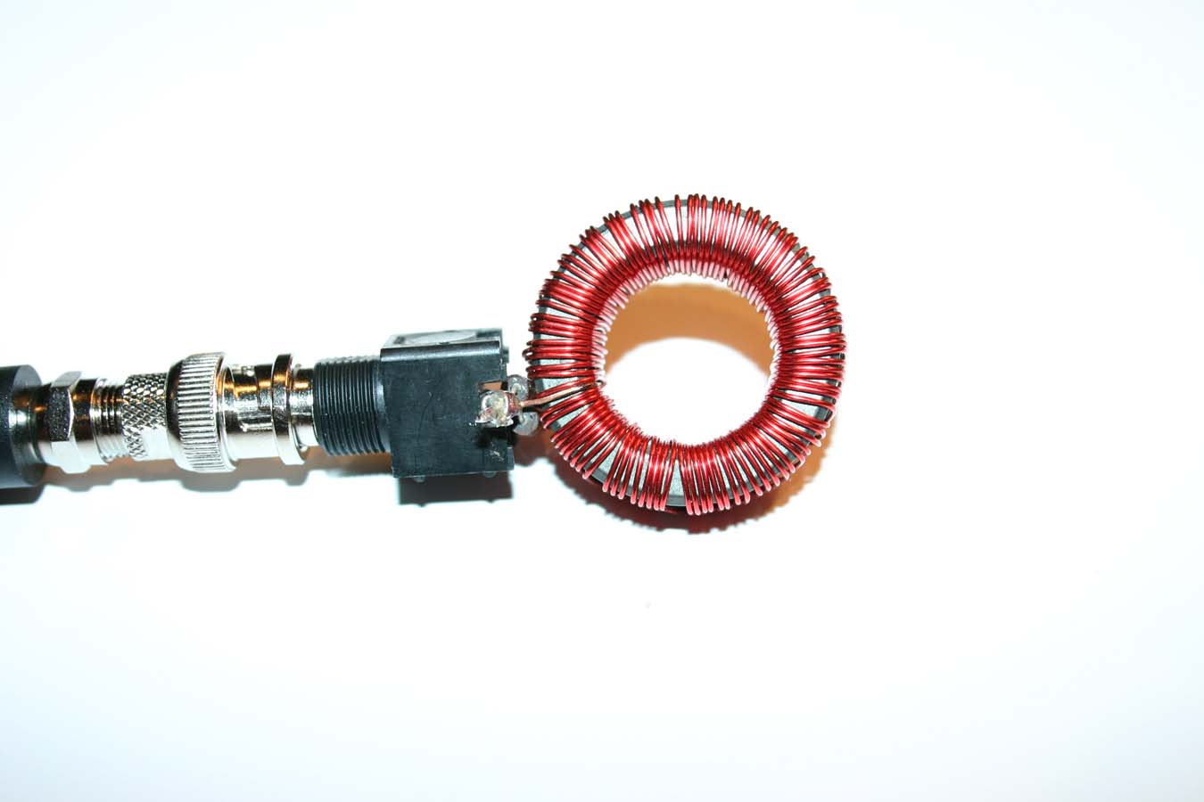
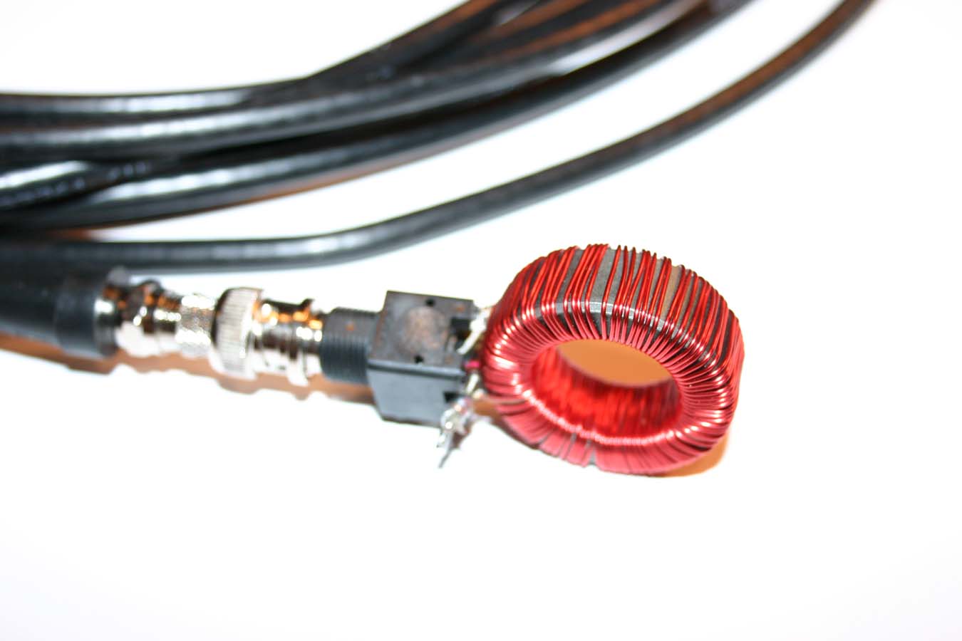
I also decided to construct a current transformer to measure the output of the marx generator. Here are photos of my current transformer. It is composed of 100 turns of magnet wire on a ferrite core. Since there are 100 turns on the ferrite core, this roughly steps down the current by a factor of 100. There is also1ohm burden resistor in parallel with the winding. Using E=IR, one can use the voltage drop across the resistor to discover the magnitude of the current that is being measured.
I also used a BNC connector to route the signal to my oscillscope. Sadly, my first attempt at measuring the output with my old analog oscilloscope didn't work well. The scope was only rated at 2MHz and it was old, so it simply wasn't up for the task.
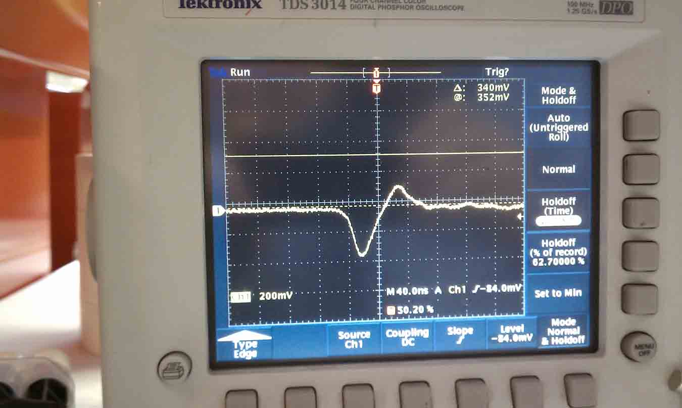
However, at UCLA Patrick Prybil and I were able to measure the output current with a professionally made current transformer and a quality oscilloscope. The output was rather surprising. The peak current was found to be 400 amps. The output also oscillated at 12.5MHz. This oscillation is due to the fact that the capacitors are discharging into a slightly inductive load. An RLC circuit is formed, which has a certain frequency of oscillation.
This scope shot is 200 amps per vertical division and 40 ns per horizontal division.
Home Page